Guitar Impedance Matching & LCR
Guitar Impedance Matching: An Introduction
The subject of guitar impedance matching and LCR values as applied to guitar circuitry can get pretty complex, so while this guide will try and keep to plain English, apologies in advance that even this ‘layman’s’ version is going to have to use a few distinctly technical terms!
This guide will begin by looking at what is happening within the guitar itself, based on passive magnetic pickups as fitted to the majority of electric guitars. It will then move on to considering the wider picture of the guitars signal chain, cables, effects boxes amps etc. So hold tight and let’s begin with some simple definitions;
> Electrical Resistance (R); The property of a circuit element (e.g. the multiple coils of wire in a pickup), that represents its ‘opposition’ to current flowing through it, for a specified electrical voltage applied across it. Measured in Ohms (or 1000’s of Ohms = K Ohms). So, for example, a device that passes 0.01 Amps when a voltage of 10 volts is applied across it is exhibiting a resistance of 10/0.01 = 1000 Ohms. Note; Many electrical devices have a resistance, not just resistors!
> Impedance (Z); The opposition, by a circuit device, to the flow of energy from a ‘source’. For varying signals, it usually changes with frequency, though in thinking guitar, it is more convenient to think of it as a reasonably constant figure (Ohms).
> Impedance matching; The practice of designing the input impedance of an electrical load (or the output impedance of its corresponding signal source) to maximize the power transfer.
> Capacitance (C); The ability of a capacitor to store charge (in an electric field). Capacitance is also a measure of the amount of electric potential energy stored. Measured in Farads (typically decimal fractions of).
> Inductance (L); The ability of an inductor to store energy in a magnetic field. Measured in Henries (H)
The easiest way to understand all this is practical examples of course. So to begin with, consider the humble single coil pickup. These are normally ‘defined’ by their DC resistance, i.e. their resistance measured at zero frequency (e.g. Direct Current as you get from a PP3 battery). What this resistance is actually indicating is the result of several thousand windings of copper wire of a (reasonably) constant cross sectional area. If the resistance of (say) 1 metre of the wire is known, as well as the total length wound on, the final total resistance is just the multiple of the two.
So far so good, but now is where things begin to get more complicated. Because it turns out that the simple act of putting all that copper wire in a tight series of coils around a bobbin introduces some new elements to worry about, coil capacitance and inductance. The results are illustrated in the diagram below. The ‘simple’ representation of a single coil pickup is shown on the far left, just a 6K Ohm (DC) resistance. But the centre diagram shows a much more realistic representation of how a pickup behaves electrically. The same old 6 K Ohm resistor is still there, but its joined by an inductance element in series and a capacitance element in parallel with it (the voltage source simply represents the fact that in use a guitar pickup generates a small voltage from the strings acting on the coils surrounding a magnet). None of these are actual ‘physical components’ you can get at inside a pickup of course, but they are measurable characteristics nonetheless.
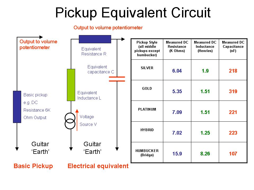
The table on the right of the diagram above illustrates real (DC) values recorded from Ironstone middle pickups belonging to different sets. The key thing to notice is that broadly, as resistance increases, it impacts inductance (L) and capacitance (C). So what?
Well, the simple answer relates to how capacitors and inductors react when different frequency signals are applied to them; remember its not just ‘resistors’ that have ‘resistance’! Simply stated, as the signal frequency increases, capacitors present less resistance to the signal, and the opposite is true for inductors. In the pickup representation then, higher frequency signals will simultaneously encounter more resistance getting to the pickups output because of the pickups inductive effect, and at the same time, the lower resistance presented by the capacitor (running from the output to ground), will increasing shunt a fraction of these higher frequencies to ground.
Additionally, the capacitive and inductive elements will have a natural ‘resonance’ point, and the output signal will peak around that frequency giving a particular characteristic to the pickups. The more coils, the higher the pickup resistance and output, but the lower the resonance point. All of this is the electrical explanation of why lower coil resistance vintage pickups sound brighter than high resistance single coils or humbuckers. There are various ways to offset this, but it’s simply the laws of physics at work!
At a more subtle level, the guitar’s own controls also have an impact. The treble roll-off with volume / treble bleed modification is well documented. The mere act of taking the guitars volume control away from its maximum alters the electrical model shown above and begins to taper off yet more treble. The solution is to add a small capacitor between the volume controls ‘hot’ side and the wiper output, thus giving higher frequency signals a path to the output even when the output wiper is turned down. What it may lack in engineering sophistication, it makes up for by being cheap and effective.
Impedance matching
So if you have followed the logic so far, its time to move on down the guitar signal chain and see what happens when things get connected together. The simplified electrical model of a pickup just presented illustrates the potentially negative impact on tone that capacitance and inductance can have inside a pickup coil. So the last thing you would want to do is add more of these elements surely? Enter the guitar cable!
Sadly, the humble guitar cable is a further source of capacitance (around 30pf per foot), again effectively operating between the guitars output and ground (just like in the diagram). Even for a very good ‘low loss’ cable, this capacitance is present and increases in value directly with cable length; twice the length, twice the capacitor value). A guitar plugged into an amplifier with a 1 metre cable will sound very different to one using a stage ‘stadium’ length cable.
Now we can return to the theme of Impedance Matching, maximizing the power transfer. Of course with small single coil pickups this is not ‘power’ with a capital P. It is again more about the effects that mismatching has on tonal quality that is the issue here (on a very low power signal in electrical terms).
To keep things simple(r), impedance in the electric guitar context in normally lumped into one of two categories; high or low where high equates to value in the order of 1M Ohm and low being 100K Ohms or less.
Normal single coil pickups are defined as ‘high impedance’ devices, meaning they are designed to work with high impedance loads, and only generate in the order of 1 to 1.5 Volts maximum output voltage (with very hard playing). So for good impedance matching, the next device in the chain (be it amplifier, effects box, mixer DI etc) should not be an electrical load on the low output pickups.
In other words these devices should have high input impedances themselves. Clearly any amplifier, stomp box etc that presents a lower impedance load to the poor old single coil pickup is going to be bad news in terms of signal degradation. Forgetting all of the tonal impacts for a second, any reduction in the (small to start with) pickup signal level is going to be compensated for by someone turning up a volume control somewhere! That will also amplify the noise in the overall signal chain, lowering the all important signal-to-noise ratio (which is exactly ‘what it says on the tin’).
So are all amplifiers, stomp boxes, mixers etc built to give a healthy high impedance load to your guitar? Well sadly no! Amplifiers are probably the most likely to present a high impedance load at their input – valve / tube amplifiers certainly tending towards the 1M Ohm end of the scale. However, mixing desks and the like are quite often specifically designed to match to low impedance microphones and similar, meaning a guitar plugged in directly without some kind of DI (Direct Injection) box is going to suffer.
True-Bypass and effects boxes
But the biggest culprit is often the humble stomp box which ideally should present a high impedance load at the front end, but can often be in the 100K Ohm level or lower. So plug your guitar into one of those via a nice long cable and you can see you are in big trouble tone-wise!
All of which leads nicely onto the pro / can arguments about ‘true-bypass’ switches. A true bypass switch does just that, it completely disconnects the effects input and output from the signal path allowing the signal to flow uninterrupted from the effects input to output jacks. From a ‘removing inherent noise when not in use’ perspective this makes perfect sense of course. But let’s assume the cable from your guitar to an effects box is 3 metres and then from effects box to the amplifiers another 6 metres.
The effects box’s low impedance output would significantly reduce the effects of the cables capacitive losses on the journey from the box to the amplifier. If the effects unit was well designed with high input load impedance, your guitar’s pickups are only facing 3 metres of cable and a matched load when the box is in circuit which is good news. But switching your stomp box to true bypass will remove that nice high impedance load on the pickups and replace it with a total of 9 metres of cable and its associated capacitive high frequency losses! Viewed in this wider context, true-bypass is not perhaps, the ‘ultimate solution’ after all.
Pre-amplifiers & Buffers
So this article has demonstrated how every stage in a guitars signal chain can, unfortunately, introduce a detrimental effect on the signal which is not a very encouraging thought. But there are ways to manage / minimize all of this. Apart from taking some care in selecting the equipment you buy / use in the first place, the most robust from of defence is some form of electronic ‘buffer’ to protect the pickups natural output tone at its source in the guitar. In this context that means an active electrical circuit as close to the pickups as possible. A well designed stomp box or multi-effects unit can also achieve this quite well (assuming it’s in the guitar to amplifier line (not the send-return loop of an amplifier). But even better are 'buffer' or pre-amp circuits built into the guitar itself (see Ironstone's own Pre-Amp Multi Effects Unit). Originally very hobbyist in nature, these are starting to become more popular. In many respects similar to active pickups, they require a good old PP3 battery hidden under the scratchplate and are normally activated by a stereo jack socket wired to turn the pre-amp on when a jack is inserted. Typically with a gain near to 1, they are not really amplifying the signal, just 'protecting' it.
And of course, having got an active buffer / pre-amp in place (and the battery installed), there are many other variants available now which can add additional drive, frequency equalization and even digital delay and similar. The active pickups supplied by EMG would be a good example of combining pickup signal buffering with complete active tone controls such as the David Gilmour (Red Strat’) inspired DG-20 pickup system with their EXG expander and SPC presence control.
So the message is clear. Its well worth spending a bit of time buffering those nice new pups to preserve the best of their tone. And while you are doing it, why not take a look at the active electronics effects market to really give your guitar project a new sound!