Stratocaster 5 Way Switch Tricks:
The humble Stratocaster 5 way switch is a much overlooked part of a Strat (or Tele or any other guitar!) hardware.
In a normal Strat configuration, the switch happily works away selecting pickups and tone filters. But once you understand how it works, the Stratocaster 5 way switch becomes a wonder of custom mod possibilities. The first thing to realise is that each unit actually contains 2 separate switches, normally electrically connected. There are 2 basic styles, shown in the diagram below, but electrically they are the same.

The diagram above is from a great feature called '5 way switches explained'. Follow the link below to check it out.
http://alloutput.com/guitar/5-way-switches-explained/
Unleash the Beast!
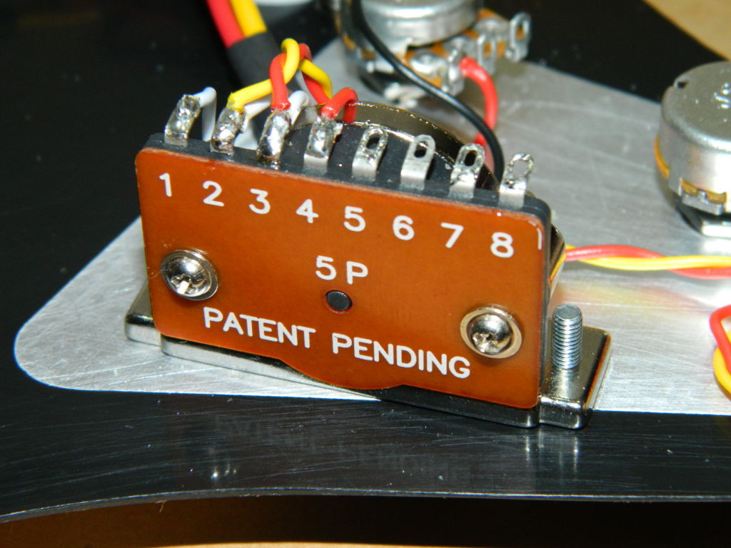
From now on I will refer to the in-line style switch numbering in the photos below to avoid confusion.

So the first thing to do is electrically separate the 2 switch parts. Which ever style of switch you have, there will be some form of connecting wire between the 2 output 'wiper' terminals of the switches (marked 4 and 5 in these photos), and normally another connection linking them to the volume potentiometer.
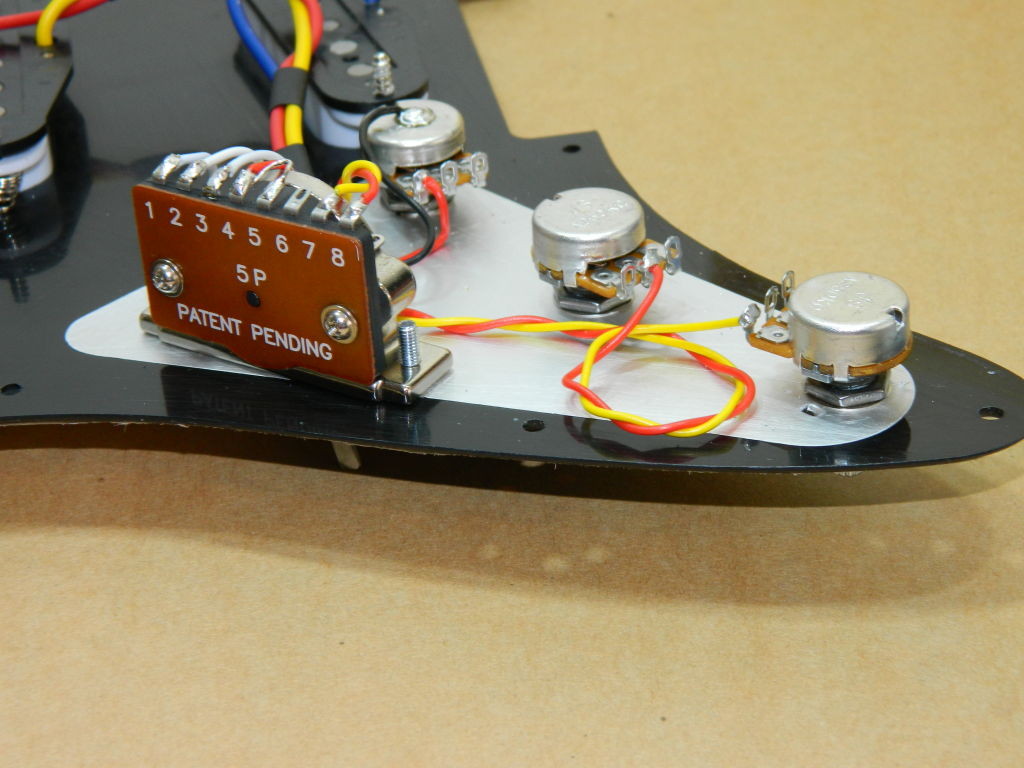
The first task then, is to remove that link between the 'wiper' tags, leaving one switch half connected directly to the pickups and the other half to the tone pots (typically just 2 of those in a standardly wired Strat). In the photo the red and yellow twisted pair are the connections to the tone pots. Ensure the link to the volume pot is coming from the '4' tag associated with the pickup half. That is the single red wire in the photo below.

Thats gives you the 2 sparated switches, so the tone pots must now be connected onto the same half of the 5 way switch as the pickups (and of course to the same relative pickup positions, middle and bridge). The photo below shows this in practise.

So now the old tone control half of the 5 way switch is completely freed up for modding use, the other half of the switch handing pickup selection and tone controls simultaneously.
To understand what can be achieved, you need to consider which of the 5 switch positions uniquely connect what to what. Referring to the standard switch number positions and the numbered switch poles in the photos then;
Switch positions 1 (i,e, selecting the bridge pickup), 3 (middle pick) and 5 (neck pickup), uniquely connects the output tag of the freed up 5 way switch (pole 5) to poles 6, 7 and 8 respectively.
Switch position 2 uniquely uniquely connects the output tag of the freed up 5 way switch (pole 5) to poles 6 & 7 (i.e. poles 5, 6 & 7 are all electrically connected together).
Switch position 4 uniquely uniquely connects the output tag of the freed up 5 way switch (pole 5) to poles 7 & 8 (i.e. poles 5, 7 & 8 are all electrically connected together).
So what can you do with these options?
Humbucker coil tapping.
If you have a humbucker in your set-up (say the bridge), its easy to use the newly freed switch to 'auto coil-tap' in switch position 2 by connecting  a ground to switch pole 6 and the humbuckers coil tap wire(s) to pole 7. As we have seen, switch position 2 uniquely joins these 2 poles together and will engage coil-tapping just in this one position.
Ibanez have a neat trick to do this on an HSH rig from a standard 5 way switch. See the bottom of the the Ironstone HSH support page;
humbucker-hss-hsh-coil-tapping
Switching in additional treble cut circuit.
A fixed resistor and capacitor connected between the main signal and ground form a treble cut circuit. Say you want switch position 4 to have a higher level of treble cut for rhythm work than either the bass of middle pickup / tone control sets normally give.
Simply connect pole 7 to the output of the main part of the switch (pole 4) and the capacitor / resistor  string of your choice to pole 8 (the other end of the resistor / capacitor pair would go to ground like any tone control wiring.
Telecaster tips and tricks.
With a Telecaster (or any 2 pickup guitar), a standard 5 way switch effectively gives you 2 extra switch positions to play with beyond simple Bridge, Bridge + Neck and Neck.
So for example, connecting the Bridge pickup to the normal 'Bridge' switch terminal and the Tele Neck pickup to what on a Strat would be the 'Middle' switch terminal gives you the normal Tele 3 way switching and leaves 2 more switch positions to experiment with.
The Ironstone Telecaster 5 way set uses an unmodified Strat 5 way switch to achieve both Parallel & Series pickup configurations as well as a simulated out of phase tone. The later is produced by inserting a small value capacitor in the signal line using the 5 way switch, to block a certain level of bass, giving rise to the distinctive thin tone. Similar levels (and more) of modification are of course possible with a Strat 'super switch', a 4 bank monster. But for most needs, clever use of a standard 5 way switch will achieve the same thing.
Other 2 pickup configurations.
To get the most out of a 2 pickup guitar with a 5 way switch, its worth starting somewhat differently. By that I mean go back to the basics of a 5 way switch actually being 2 separate switches that step through the terminals together. So think about one pickup being dedicated to one half of the 5 way switch and the other pickup wired to the other half. For this sort of set up you will need to keep the 2 'outputs' terminals (4 & 5) connected so that in at least one switch position, both pickups are supplied to the volume control.
In Conclusion:
So there you have some ideas for 'de-constructing' how a standard 5 way switch operates, and the sort of things that can be achieved.
There are plenty of ideas and schematics on the internet if you hunt them down.
A site that Ironstone have recommended before as a great resource is;
phostenixwiringdiagrams


Have Fun!

Hi Tony, Great blog! I would like to use the treble cut circuit to tame the brightness of my middle and neck pickups. I’m doing this to match the tone of the bridge pickup which is slightly darker. I still want to use my master tone to control all the pickups at once but I just want the pickups to be better matched in brightness. The pots are 500K. Do I need to wire a resistor and cap in series or parallel? Any idea of which values I should use? At the moment they are fairly close. Within 3 numbers on the knob/dial. Thanks for any help that you can give me.
Dan
Hi Dan, Glad to hear you liked the Blog. If I understand you correctly, what you want is indeed possible (I assume you want to keep the master tone control active for all 3 pups), with the re wired 5 way giving more treble cut to the Neck / Neck+Middle / Middle / Middle + Bridge combinations). You are effectively lowering the resistance of the tone pot by shunting a resistor in parallel with it for those 5 way switch settings.
Start by isolating one half of the 5 way as I have described. Its easier in your case as you have a single wire from the tone pot to reposition if needed. Now the fun!
Referring to the same number scheme I have used before, connect pins 7 and 8 together and then to the guitar earth. Now connect a single resistor (start with a 1MOhm) between the wiper (middle) terminal of the tone pot and the 5 way switch wiper terminal 5. So now the Bridge 5 way switch position will give treble cut as normal based on the normal master tone setting. All the other 4 switch settings will have a reduction in the effective value of resistance of the tone pot and thus a greater level of treble cut. The value of the additional resistor is a guess. increasing its value (say 2MOhm) will lessen the level of treble cut. Hope that helps. Cheers, Tony